Back in beta! Stay tuned.

Standards

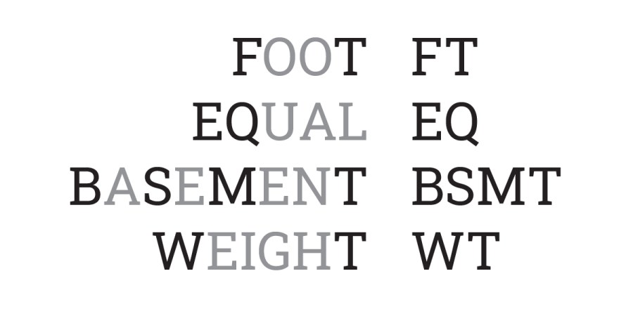
General Use Abbreviations

Three simple human figures with speech bubbles above them display SOW?, RTU., and EOD?!—common drawing set abbreviations often seen as construction abbreviations or workplace jargon.

Navigating the world of architectural and construction abbreviations can be tricky, especially when deciphering casual communications like emails or on-site meeting discussions. Our "Miscellaneous Abbreviations" resource provides a concise, ready-reference list to help clarify common industry acronyms. This evolving compilation is designed to be a practical tool, ensuring you're always in the know, even when industry jargon gets dense.

Color

A circular diagram divided into ten equal segments, each shaded in varying tones of gray from light to dark, arranged in a gradient around the ring.

Color fundamentally shapes our perception of architectural spaces, influencing mood and functionality. This excerpt delves into how light quality, cultural contexts, and even branding impact color's appearance. Understanding the distinctions between additive and subtractive colors, the nuances of hue, value, and intensity, and the dynamics of complementary colors are essential for architects to strategically employ color in creating impactful and effective environments.

Wall Partition Types

Two black-and-white diagrams of cellular structures side by side, each with a hexagonal label marked ??? pointing to a specific part of the structure within the vertical columns, resembling different wall partition types.

Effective wall labeling is crucial for clear construction documentation. This guide explores various approaches to classifying interior partition walls, from simple designations to complex, formula-based systems. Understanding the pros and cons of each method, along with considerations for fire-resistance ratings, acoustics, and detailed sheet notes, helps architects choose the most consistent and efficient documentation standards for their projects.

Insulation R-Values Chart

Two side-by-side rectangles, one above the other, separated by a horizontal line. The top rectangle, marked with vertical lines, is labeled 4.5 R-Value; the bottom, with a zigzag pattern, is labeled 2.8—great for an insulation diagram or R-Values chart.

This detailed chart outlines various thermal insulation types and their estimated R-values, crucial for precise space calculations in architectural design. Given the continuous advancements in insulation technology, it's vital to verify product specifications against design minimums on-site. This resource is regularly updated, and we welcome suggestions to ensure its accuracy and comprehensiveness for industry professionals.

Open to Below; Open to Above

A large solid-lined square and a smaller solid-lined square appear on a white background. Both squares, marked “Open to Below,” have diagonal lines inside. Dashed lines connect their corners, outlining a larger rectangle.

Deciphering "open to below" and "open to above" in architectural plans is crucial for clarity. "Open to below" areas, visible within the view range like floor openings or shafts, are delineated with solid lines and an "X" mark. Conversely, "open to above" spaces, such as multi-story atriums or soffits, are represented by dashed lines, indicating elements not directly seen in the current plan view. Understanding these graphic standards ensures precise communication in architectural documentation.

Industry Graphic Standards

A large clipboard icon with checkmarks is on the left. On the right are six diagrams showing boxes in various orientations and three grid patterns, reflecting Industry Graphic Standards. The background is white.

Graphic standards in architectural documentation are dynamic, constantly evolving with project needs and office conventions. While internal guides are essential, a commitment to industry consistency enhances legibility and streamlines collaboration. These standards, developed through diverse project experiences, aim to provide a flexible framework, encouraging adaptation and refinement to best serve the unique communication goals of each drawing type.

Hardwood & Softwood Charts

A table with two rows and three columns. The first row shows a globe, a wavy pattern, and the text “A, B.” The second row features a pine tree for softwood, a geometric line pattern, and the text “B, E.” Perfect for visual charts.

Understanding wood characteristics is crucial for architectural design. This comprehensive chart details various hardwoods and softwoods, outlining their scientific names, common variations, and key properties. From the durable strength of Oak for flooring to the aromatic decay resistance of Cedar for outdoor applications, this guide helps professionals select the ideal wood type for specific structural and aesthetic requirements, acknowledging that properties can vary based on species and processing.

Conformed Set

Nine document icons form two diagonal lines, each representing a Conformed Set. The first line shows documents labeled 1, 2, 3 three times, while the second line repeats 2, 3, 1 three times.

Understanding a "conformed set" is crucial for architects and design professionals. This artificial drawing set, never formally issued, compiles the latest updated sheets from various bulletins into one comprehensive document. Unlike simply printing from design software, a conformed set ensures all revisions are accurately represented, providing a clear, up-to-date snapshot of the project's progress without the risk of showing unvetted changes or incorrect revision bubbles.

Drawing Set Abbreviations

Four words—FOOT, EQUAL, BASEMENT, and WEIGHT—are each shown in full with their drawing set abbreviations: FT, EQ, BSMT, and WT, arranged in two columns on a white background.

Achieving consistency in architectural drawing sets is paramount, especially when using abbreviations. While specific abbreviations may vary between offices, the key lies in maintaining uniformity throughout a project's documentation. Listing all chosen abbreviations at the beginning of your drawing set, and ensuring new team members review them, is crucial for preventing frustrating inconsistencies and streamlining the design and construction process.

Engineering Drawing Scales Printed Size

A graphic features a scale, pencil, and ruler above the word engineering in bold, black lowercase letters—simple black line drawings that evoke the precision of Engineering Drawing.

Understanding engineering scales is crucial for accurate architectural representation. This guide provides a comprehensive reference for how designs translate from digital to print, offering clear insights into various scale values and their corresponding "real" sizes. Engineers and architects alike can utilize this resource to ensure precise documentation and effective communication of large-scale projects, optimizing workflows and minimizing errors.

Architectural Drawing Scales Printed Size

A black and white image with a scale icon, a crossed pencil and ruler icon, and the word architectural—referencing architectural drawing scales—written below in bold, sans-serif font, ideal for emphasizing printed size accuracy.

Understanding architectural scales is fundamental for accurate design and printing. This comprehensive guide details various architectural scales, from 12" = 1'-0" to 1" = 100'-0", providing their corresponding fractions, units, and ratios. It also includes practical tables illustrating how real-life dimensions translate to printed sizes at common scales, essential for professionals and students alike.

Slopes & Ramps

A series of nine horizontal black lines with varying angles and spacings, some solid and some dashed, are arranged on a white background. The lines become increasingly slanted from top to bottom, resembling a set of abstract slopes.

Understanding slopes and ramps is crucial for architectural design and construction. This comprehensive guide details nominal and actual dimensions for common lumber sizes, essential for accurate planning. We also delve into critical slope principles, including pitch, percentages, and degrees, alongside practical rules of thumb for drainage and unpaved surfaces. Ensure your projects meet both aesthetic and functional requirements with precise slope calculations.

Lumber Sizes

Three rectangular prisms of increasing sizes are drawn in black outline. Each prism, resembling stacked lumber, features diagonals connecting the corners of their front and back faces, forming an X shape on each end.

Understanding lumber sizes is crucial for accurate architectural design and construction. While nominal dimensions (like 2x4) are commonly used, the actual size of dried lumber differs due to moisture evaporation. This reduction is consistent, not a percentage, meaning larger pieces also shrink similarly. This guide clarifies the distinction between nominal and actual lumber dimensions, providing essential information for professionals to ensure precise material specification and avoid common pitfalls.